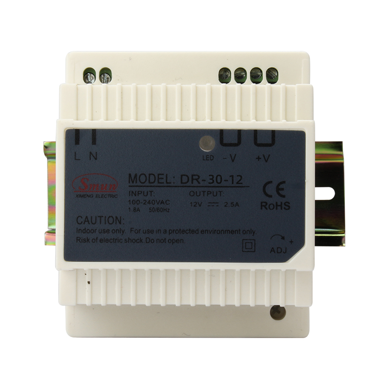
DR-30
SMUN
Description:
The DR-30 is a commonly used rail-mounted switch mode power supply, extensively applied in fields such as industrial automation, electrical control cabinets, LED lighting, and security surveillance. Below is a general introduction and overview of its features:
Output Power: Standardly provides 30W of stable DC power output.
Input Voltage Range: Supports a wide input voltage range, e.g., 85-264VAC or 120-370VDC, adaptable to diverse grid conditions.
Output Voltage: Common output voltage options include 5V, 12V, 24V, etc., depending on the specific model.
Efficiency: High-efficiency design, above 80%, effectively reducing energy consumption and heat generation.
Installation Method: Utilizes DIN rail mounting, compliant with the standard 35mm rail mounting system, facilitating integration into control cabinets or panels.
Protection Functions:overvoltage, overcurrent, and short circuit protection mechanisms, ensuring the safety of both the power supply and load equipment.
Operating Temperature Range: Designed for a wide temperature range, generally from -20°C to +70°C, suitable for various industrial environments.
Certifications: Most products are certified by CE, TUV, and other international safety standards, conforming to global standards.
Industrial Automation: Powers PLCs, sensors, actuators, and other control components.
LED Lighting: Supplies stable power to small to medium-sized LED lighting fixtures.
Security Surveillance: Powers CCTV cameras, access control systems, and other security equipment.
Communication Equipment: Suitable for small-scale switches, routers, and the like.
Instrumentation: Provides power support for various measuring and testing equipment.
Specifications:
Model | DR-30-12 | DR-30-24 | DR-30-48 | |
Output | DC Voltage | 12V | 24V | 48V |
Current Range | 0-2.5A | 0-1.25A | 0-0.63A | |
Rated Power | 30W | 30W | 30W | |
Ripple Noise(Max) | 80mVp-p | 100mVp-p | 120mVp-p | |
Voltage Adj.Range | 12-15V | 24-30V | 48-55V | |
Voltage Tolerance | ±1.5% | ±1.0% | ±1.0% | |
Line Regulation | ±0.5% | ±0.5% | ±0.5% | |
Load Regulation | ±1.5% | ±1.0% | ±1.0% | |
Set up,Rise time | 500ms,30ms/230VAC 1000ms,30ms/115VAC(full load) | |||
Hold up Time | 60ms/230VAC 12ms/115VAC(full load) | |||
Input | Voltage Range | 85 ~264VAC 120~370VDC | ||
Frequency | 47 ~ 63Hz | |||
Efficiency | 77% | 80% | 82% | |
AC Current | 0.55A/115VAC 4A/230VAC | |||
Inrush Curent | 40A/230VAC | |||
Leakage Current | <1mA / 240VAC | |||
Protection | Overload | 105 ~ 130% rated output power | ||
Protection tye:Constant current limiting,recovers automatically after fault condition is removed | ||||
Over Voltage | 14-17V | 29-33V | 56-65V | |
Protection type : Shut off o/p voltage, re-power on to recover | ||||
Environment | Working Temperature | -10~ +60℃ (Refer to derating curve as datasheet from SMUN) | ||
Working Humidity | 20 ~ 90% RH non-condensing | |||
Storage Temp.Humidity | -20 ~ +85℃, 10 ~ 95% RH | |||
Temp.Coefficient | ±0.03%/℃ (0 ~ 50℃) | |||
Vibration | Component:10~500Hz,2G 10min./1 cycle,60min. each along X,Y,Z axes | |||
Safety | Safety Standards | CE and GB4943.1 Safety standard | ||
Withstand Voltage | I/P-O/P:1.5KVAC I/P-FG:1.5KVAC O/P-FG:0.5KVAC | |||
Isolation Resistance | I/P-O/P, I/P-FG, O/P-FG:>100M Ohms / 500VDC/25℃/70% RH | |||
EMC Emission | Compliance to EN61000-3-2:2014/EN61000-3-3:2013 | |||
EMC Immunity | Compliance to EN55032:2015/EN55035:2017/60950-1 | |||
Others | MTBF | ≥327.9K hrs MIL-HDBK-217F(25℃) | ||
Dimension | 93*78*56mm (L*W*H) | |||
Packing | 0.25Kg; 60pcs/15Kg | |||
Note | 1. All parameters NOT specially mentioned are measured at 230VAC input, rated load and 25℃ of ambient temperature. 2. Ripple & noise are measured at 20MHz of bandwidth by using a 12" twisted pair-wire terminated with a 0.1uf & 47uf parallel capacitor. 3. Tolerance : includes set up tolerance, line ragulation and load regulation. 4. The power supply is considered a component which will be installed into final equipment. The final equipment must be re-confirmed that it still meets EMC directives. 5. Installation clearances : 40mm on top, 20mm on the bottom, 5mm on the left and right side are recommended when loaded permanently with full power.In case the adjacent device is a heat soure, 15mm clearance is recommended 6. Derating may be needed under low input voltage. Please check the derating curve for more details. 7.Please contact with SMUN customer service for more details. |